
The ISAC β-NMR HomePage
| Introduction to β-NMR |
Publications |
Students Projects |
Contacts |
| Technical Information |
Data Acquistion |
Approved Experiments |
Internal Page |
| Related Links |
BNMR Wiki |
Data Analysis |
Photo Album |
|
|
Starting Up the βNMR cryostat
Assuming the cryostat is warm (room T) throughout and disconnected from the Helium dewar, but connected to the temperature controller (heater and sensor).0. Schematic Operation:
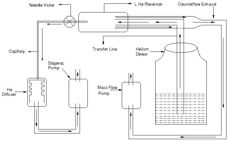
An schematic diagram (not to scale) is shown below. Liquid helium is drawn from the "Helium Dewar" to "L He Reservoir" through the "Transfer Line". A "needle valve" connects the transfer line and the "L He Reservoir". The valve is used to control the amount of Helium entering the reservoir and is controlled through the "camp". The transfer line consists of concentric flow pipes where the outer pipe is connected to the "counterflow exhaust". The inner line of the tranfer line is cooled by the counterflow which is connected to a diaphragm (i.e "Mass flow") pump. The "mass flow" may be controlled and be read via the "camp".The liquied Helium reservoir is connected to the sample space which, in turn, is connected to the powerful Sogevac pump. This pump is used to cool down the sample.
The arrows inside the tubes/transfer line show the direction of Helium gas.
1. Preparation
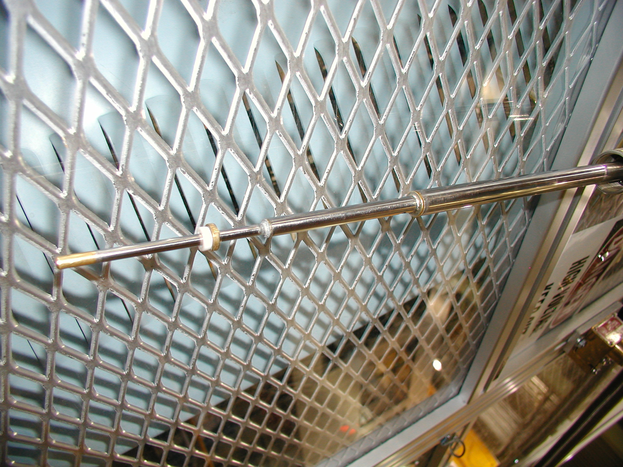
Crane in a He Dewar if necessary. This requires a crane operator and some available He dewar (and thus some prior planning). You must open the hatch in the roof of the cage. Remember to ground the He dewar if you are going to float the platform.2. Install the Counter Flow Helium Transfer Line
The transfer line looks like this: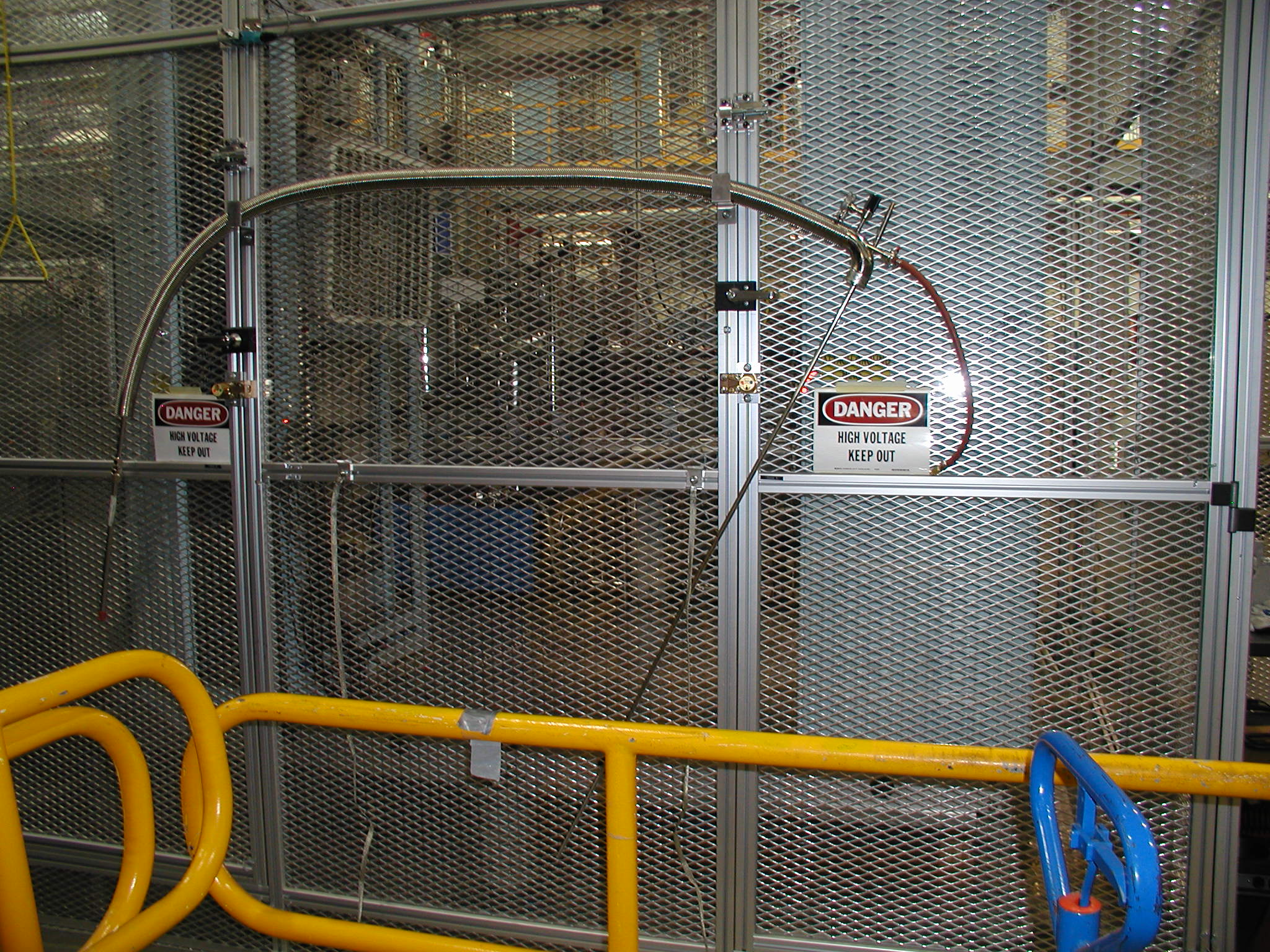
Helium is drawn out of the dewar through the long end of the line into a reservoir in the cryostat and the cold vapour is drawn back through the line to the orange rubber hose seen on the right in this picture.
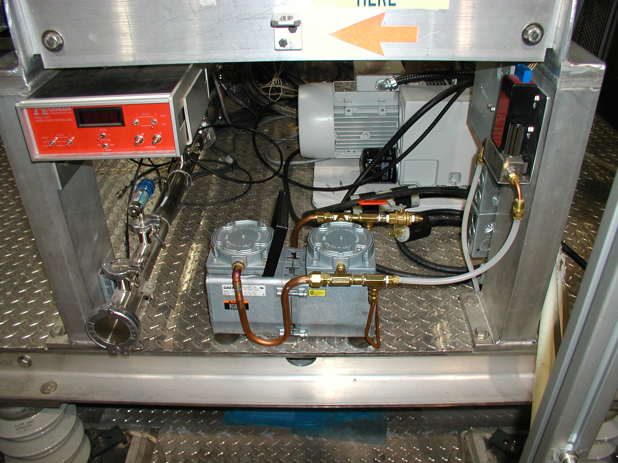
This Helium circulation is accomplished by the small diaphragm pump:
To install the transfer line:
A. Check that you have the correct adapter for the dewar and transfer line. Check that you have the wooden support for the transfer line. Have some teflon tape in case the seal is not good. Install the step ladder if necessary.
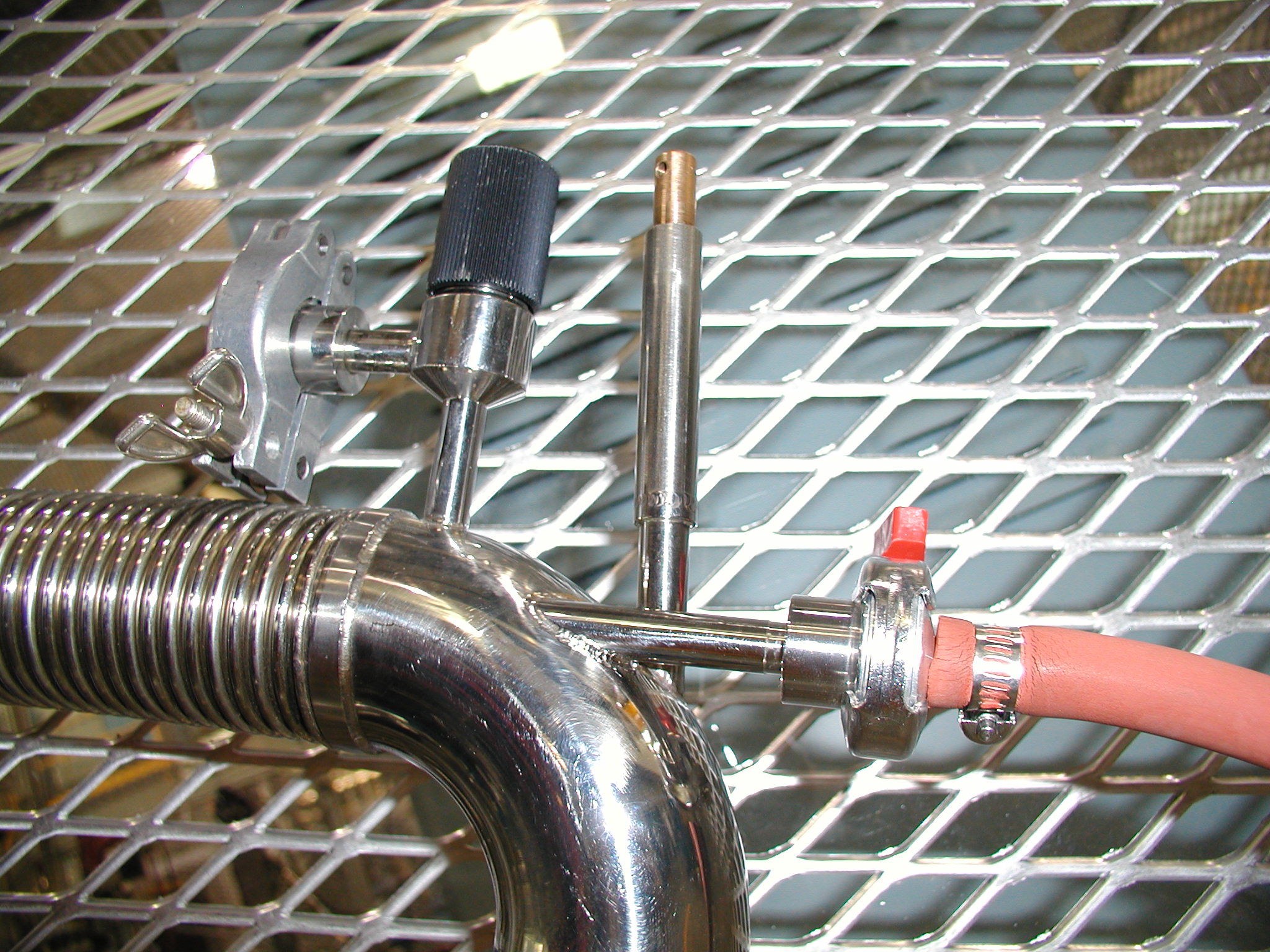
B. Make sure the manual needle valve on the inlet side of the transfer line is open. The Needle Valve is the vertical brass knob, between the vacuum space pumping port and the counterflow exhaust (orange tube):
B. Slowly introduce the transfer line into the dewar. When there is some pressure (not to exceed 5 psi) in the dewar, there should be flow through the line. Remove the protective cover to expose the FRAGILE cryostat end of the transfer line which looks like this:
You should feel some He gas flowing to the very tip. Once you are sure this is the case, and that the teflon seal is on the tip as shown,
C. Carefully put the transfer line into the cryostat, by removing the cap on the port and inserting the tip. If the line gets stuck, try rotating it about the port. When it is in, tighten the stainless connector. As the transfer line cools the teflon seal will contract and the connector nut will need to be tightened again.
D. Connect the white polyflow tube (connected to the diaphragm pump) to the orange tube at the top of the dewar.
The transfer line is now installed.
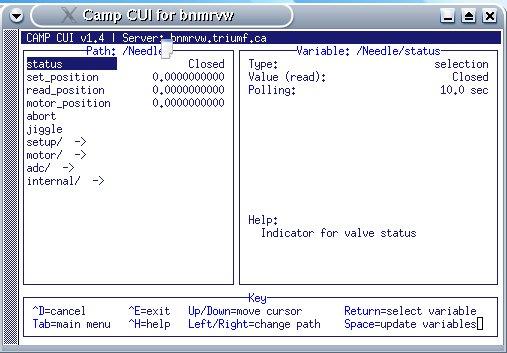
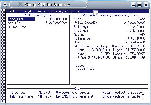
3. Make sure the Needle Valve Controller is zeroed.
Go into "setup" and find "zero"
4. Check that there is flow through the cryostat
The cryostat is cooled by pumping a small flow of LHe out of the
reservoir through the automatic needle valve into a capillary leading
to the "block" a sintered piece of copper which is the coldest part of
the operating cryostat. This is done with the high powered Sogevac pump: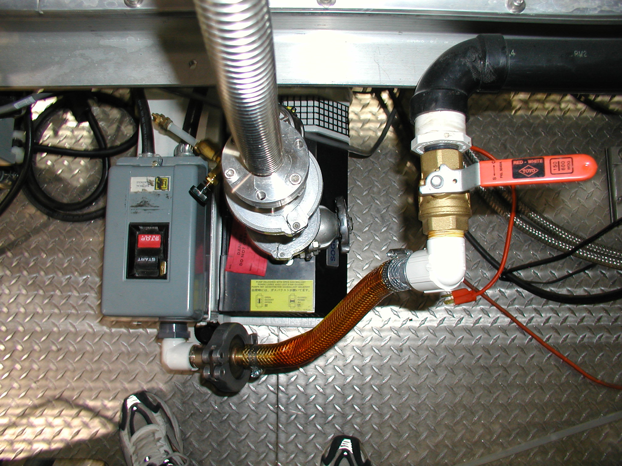
A Start up the Sogevac (pumping line assumed connected)
i) Open the Sogevac exhaust to the He return line (red valve on the right above and valves on the outside of the cage near the EL3 coldhead)
ii) Turn on the pump with the switch (left above).
iii) Open the big aluminum handled valve on the pump inlet - watch the pressure come down on the gauge at the inlet
B. Make sure the cryostat needle valve is closed. Then valve off the Sogevac. If the NV is not leaking the vacuum gauge should stay put.
C. Using CAMP, open the NV to 1 turn. Check that the pressure at the Sogevac climbs to atmosphere. If the transfer line is cold, the pressure should climb more quickly.
How long should it take for a warm Xfer line (He gas) vs cold Xfer line for a given NV setting ?
5. Flush the cryostat with He
Repeat the above cycle (4.) a few times, then leave the Sogevac valved off. This should prevent the NV from clogging with frozen water and/or air.6. Start up the diaphragm pump
A Check that it is connected correctly: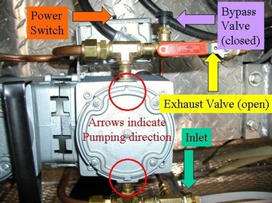
B. Make sure the cryostat NV is closed. Switch the diaphragm pump ON
C. In CAMP set some high mass flow value like 30 l/min. With a warm transfer line, the pump will not be able to pull this rate, but when the line is cold and liquid is flowing through the flow rate will reach this value. The flow meter should read some value above its zero (~5 l/min) though.
The transfer line is now cooling. This will take half an hour or so. Make sure the transfer line is low enough in the dewar to access the liquid.
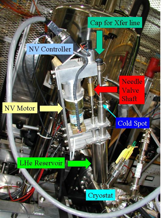
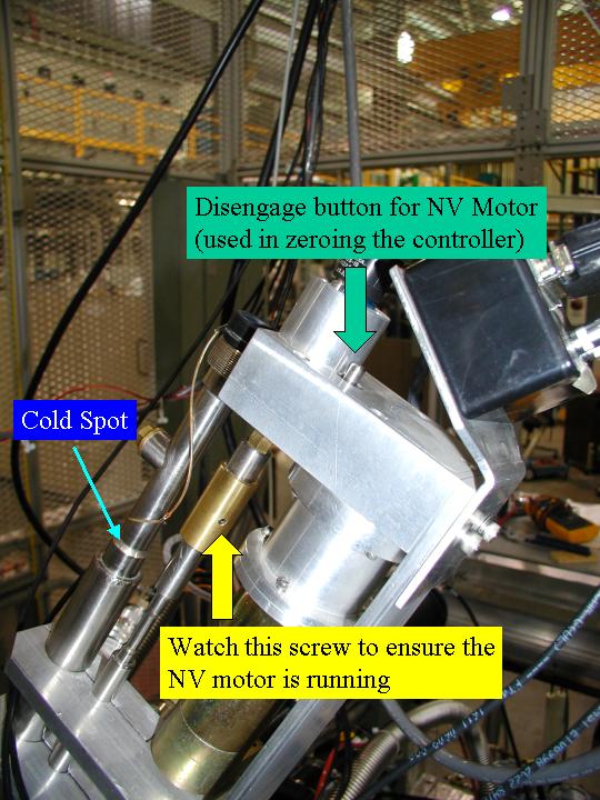
After some time the flow rate will get to 30 and the reservoir will fill. The cold spot on the transfer line port will begin to get cool, and condensation (and even ice) will form there.
Eventually the orange rubber hose will also frost up, indicating a good flow of liquid through the line.
7. When the transfer line is cold, begin cooling the cryostat
Page last modified: 07/23/09 02:45 by Andrew MacFarlane.