
The ISAC β-NMR HomePage
| Introduction to β-NMR |
Publications |
Students Projects |
Contacts |
| Technical Information |
Data Acquistion |
Approved Experiments |
Internal Page |
| Related Links |
BNMR Wiki |
Data Analysis |
Photo Album |
|
|
Setting up the High Field Spectrometer for Low Frequency Sweep
Note: Before you start make sure the
the Berkeley Nucleonics Corp AFG
and/or the magnet are set up correctly in Camp. The correct setting are
saved in "bnmr_05042004", which can be loaded by opening a camp window,
press on the "Tab" button, choose "configure", then "Open config file"
and "bnmr_05042004". This will make the AFG available under the path
"/frq" and the magnet under "/Magnet".
Instead of using the "Freq" mode button - we use the "Camp" mode. However, there are two different camp devices that may be used in a camp sweep experiment,
Instead of using the "Freq" mode button - we use the "Camp" mode. However, there are two different camp devices that may be used in a camp sweep experiment,

- The arbitrary function generator (FG)
- The magnetic field (MG)
- FG - for a frequency sweep
- MG - for a magnetic field sweep
- For frequency sweep: "Expert" -> "CampSweepDev" -> "frequency generator" and set the value of "Camp path" to /frq
- For magnetic field sweep: "Expert" -> "CampSweepDev" ->
"magnet" and set the value of "Camp path" to /Magnet
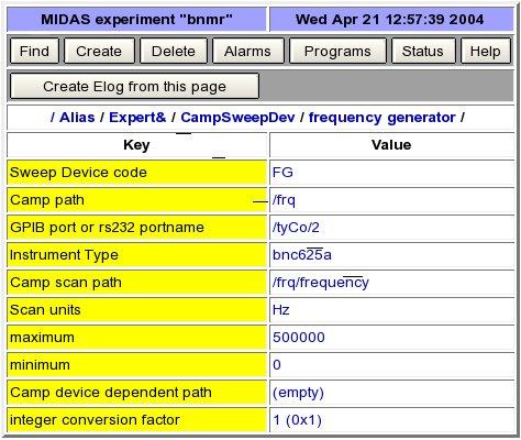
In the frequency sweep we use the
Berkeley Nucleonics Corp to generate
the RF. "Telulex Model
SG-100/A" frequency generator. In CAMP, this is known as the bnc625a.
Its front panel looks like this:
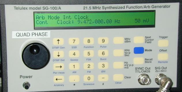
This unit needs to be
- powered: is obvious, and when it's on the screen is yellow.
-
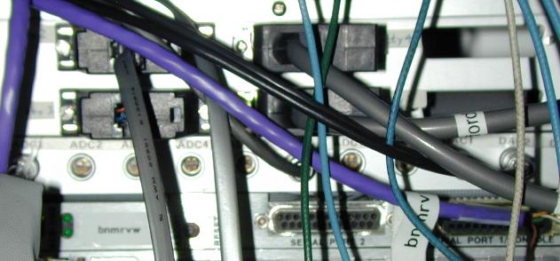
cabled to the serial interface of the camp MVME162 computer (bnmrvw), the cabling is done via a telephone-style patch cable. On the platform it looks like this - the cable going into the connector in the top-left here (/tyCo/2)
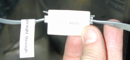
The patch cable requires a "crossover" box shown below
- have its output sent to the low frequency RF power amplifier. A
bnc cable is required to go to the input of the low frequency power
amplifier.
The low frequency power amplifier we
are currently using is the EIN
model 1040L which
is normally in the low field spectrometer rack. It has a normal single
phase
three-pronged power plug, but it is very heavy, so be careful if you
move it around to the platform.
The front panel is quite obvious and it looks like this.
The front panel is quite obvious and it looks like this.
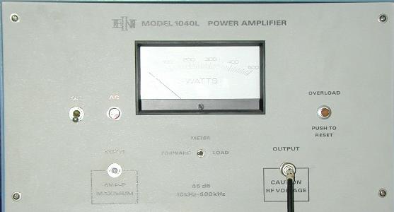
Note this "push-pull" amplifier is
quite nonlinear at higher
amplitudes. Practically the amplitude of the linear region is limited
to 50 mV on the camp amplitude control for the bnc frequency generator
- unless you can tolerate significant distortion.
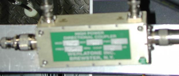
We usually place the Werlatone directional coupler in series with the high power output. Note directional is real. There is an input and an output of this unit. Both N-type connections. There are also bnc connections for monitoring the reflected and transmitted power (through 40 dB attenuation - which makes it safe to attach to a scope). We do in fact usually monitor the RF system by doing this.
Note the range of this coupler is 10 kHz - 250 MHz, so you may need to remove it for the lowest frequencies.
The Directional Coupler looks like this:
Once all this is cabled together and
powered (actually leave the amp
off til you are really ready), one has to set up CAMP to talk to the
device. Once the interface is setup, you should now be able to set the
device
"online". The camp device looks like this
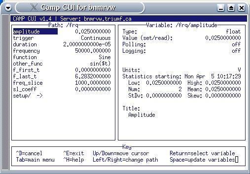
Note - for linear region keep the
amplitude parameter no greater than
0.05 V. Unless you know what you are doing, you may choose one of two
possible functions, "Sine" ot "Sine_1_3". Do not use the "other_func"
option to set the waveform. The maximum frequency is determined by the
num_pts value in the "setup" screen. A lower number allowes higher
frequencies. The "setup" screen looks like this.
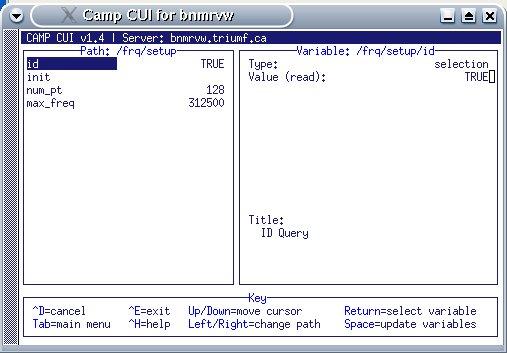
Note that the low frequency amplifier
is limited to frequencies below
500kHz.
Have a look at the output of the frequency generator check that it sweeps over the range, then power up the amplifier.
Note there is no safety interlock for the low frequency RF system, so be careful not to apply too high voltages, and be sure the RF coil is terminated with the high power 50 ohm load.
Page last modified: 07/23/09 02:45 by Andrew MacFarlane.