
The ISAC β-NMR HomePage
| Introduction to β-NMR |
Publications |
Students Projects |
Contacts |
| Technical Information |
Data Acquistion |
Approved Experiments |
Internal Page |
| Related Links |
BNMR Wiki |
Data Analysis |
Photo Album |
|
|
Calibration of the Low Field Spec. Magnet (ILE2A1:HH)
Conversion from Current to Field
Enter either the current of the field, then click
outside
the text box.
| H=A+B*I A=0.175+-0.046 G; B=2.2131+-0.0019 G/Amp where H is the field in G and I is the setpoint current in Amps. |
Details of Calibration
The magnet is controlled by EPICS, where the setpoint is sent in Amps.
The read back from this magnet deviates from the setpoint linearly with
the value of the setpoint: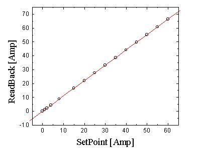
Fig. 1: The readback as a function of the setpoint of the current in the magnet. The linear fit is
R=A+B*S, A=-0.036+-0.014 Amp, B=1.106+-4.4e-4
R is readback and S is setpoint. (Download data)
The actual value of the
current that
runs in the magnet is closer to the setpoint that the read back, so
this is the value that we will use to calibrate the magnet, i.e. conver
current in Amps to field in Gauss. The calibration itself was performed
by looking at 8Li resonance in an annealed Au
foil as a
function of
different currents (year: 2002, RUNS: 45099-45103, 45110).
The resonance lines where found to be Gaussian!, to be more exact two Gaussian lines. The center of the line was taken from the narrow line of the two. The center of the narrow line as a function of the setpoint current is presented in Fig. 2.
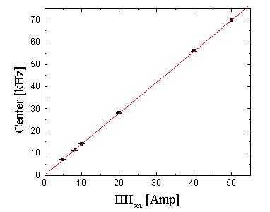
Fig. 2: The center of the narrow line as a function of the setpoint current. The linear fit is
C=A+BI, A=0.11+-0.03 Amp; B=1.395+-0.0012 kHz/Amp
C is the center in kHz and I is the current in Amps. (Download data)
The resonance lines where found to be Gaussian!, to be more exact two Gaussian lines. The center of the line was taken from the narrow line of the two. The center of the narrow line as a function of the setpoint current is presented in Fig. 2.

Fig. 2: The center of the narrow line as a function of the setpoint current. The linear fit is
C=A+BI, A=0.11+-0.03 Amp; B=1.395+-0.0012 kHz/Amp
C is the center in kHz and I is the current in Amps. (Download data)
To get the value of the
field in G
corresponding to a setpoint in Amps, we devide the center by the
giromagnetic ratio of 8Li, γ=0.63018
kHz/G.
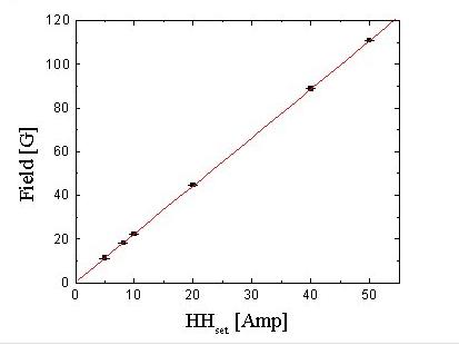
Fig. 3: The field in G as a function of the setpoint in Amps. The linear fit is:
H=A+B*I, A=0.175+-0.046 G; B=2.2131+-0.0019 G/Amp
H is the field in G and I is the setpoint current in Amps. (Download data)

Fig. 3: The field in G as a function of the setpoint in Amps. The linear fit is:
H=A+B*I, A=0.175+-0.046 G; B=2.2131+-0.0019 G/Amp
H is the field in G and I is the setpoint current in Amps. (Download data)
| H=A+B*I A=0.175+-0.046 G; B=2.2131+-0.0019 G/Amp where H is the field in G and I is the setpoint current in Amps. |
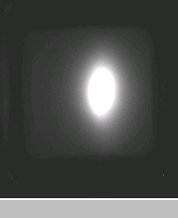
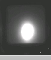
The applied magnetic field in bNQR from the Helmholtz coil is perpendicular to the incident ion beam. Thus, as the ion beam enters the field, it suffers a vertical deflection due to the Lorentz Force. Actually the ions will make a a circular path with a certain radius of curvature R, but R is much bigger than the size of the magnet, so the deflection is rather small (as the field is not very large) but it is significant for small samples. The attached plot shows a calibration of the vertical beamspot deflection (measured using the scinitillator and camera) as a function of field. The shift can be up or down depending on the polarity of the magnet. To reverse the polarity one has to reverse the leads physically on the power supply. Currently the deflection is downwards (Oct.2006). In order to compensate for the deflection, we can 1) move the cryostat or 2) have a different tune for each field with the electrostatic correction benders compensating. We are currently using method 1. The calibration plot allows this to be done easily, using a reference point on the camera image. Note that when we begin to decelerate on bNQR, this problem will be much more serious, as R is proportional to (velocity/magnetic field).
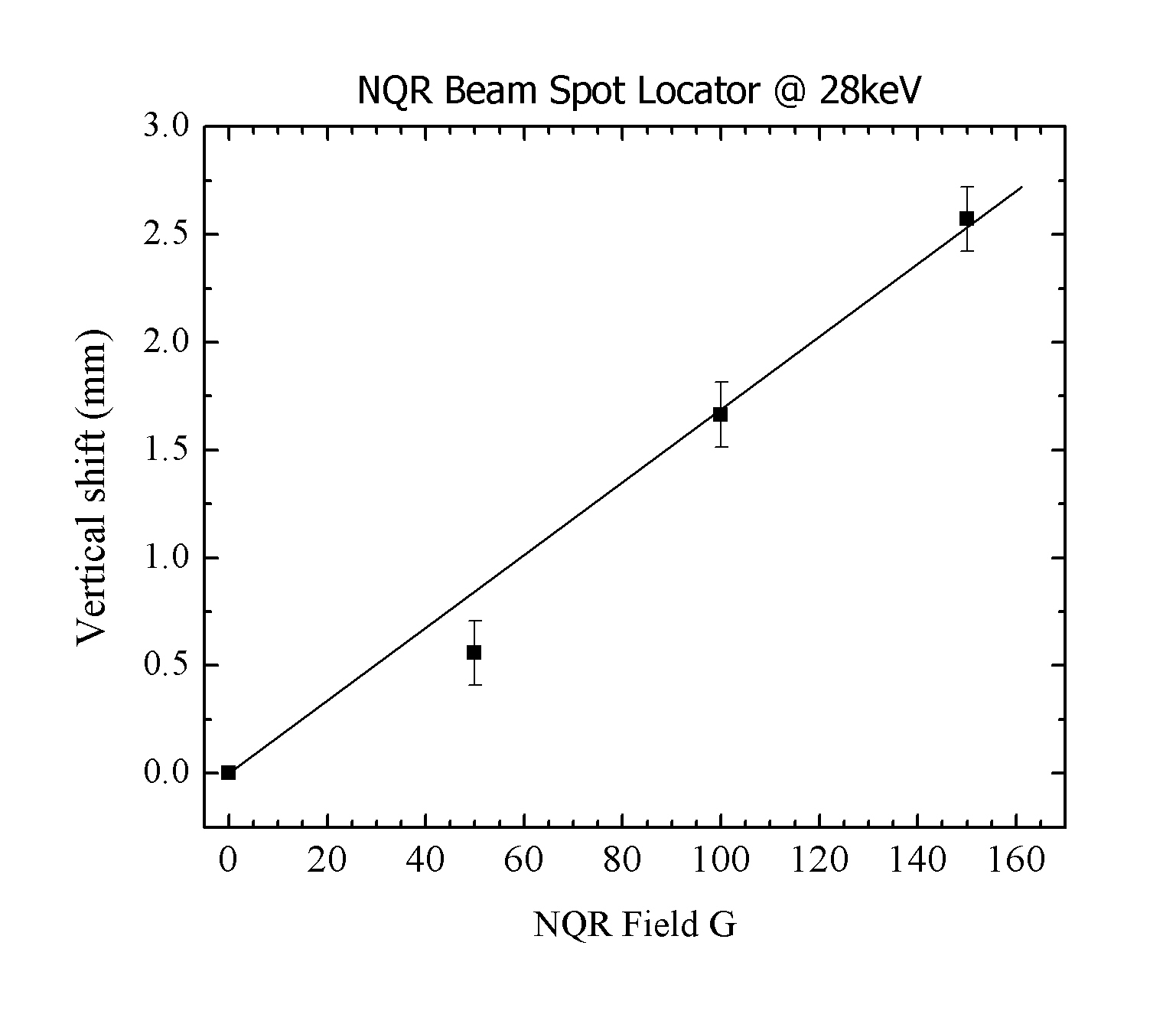
Bending of Beamspot
(1)Zero Field (ZF) Beam-Spot
(2)150G Beam-Spot
Page last modified: 07/23/09 02:45 by Andrew MacFarlane.