
The ISAC β-NMR HomePage
| Introduction to β-NMR |
Publications |
Students Projects |
Contacts |
| Technical Information |
Data Acquistion |
Approved Experiments |
Internal Page |
| Related Links |
BNMR Wiki |
Data Analysis |
Photo Album |
|
|
Running BNMR and BNQR in Dual Mode using the Fast Switching
Setting up the beam
To set up the timing for the beam period delivered to BNMR and to
BNQR ask an operator to open the "IMS kicker / BNMR/BNQR switching"
dialog from the Epics main page:
The dialog looks like this
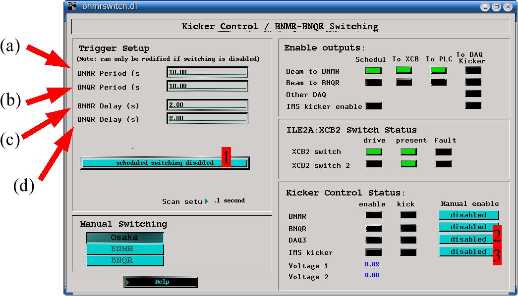
(b) The period of beam delivered to BNQR (in seconds).
(c) Delay after BNMR beam period to allow helicity flip (if needed). This can be set to zero and cannot be longer than BNMR period.
(d) Delay after BNQR beam period to allow helicity flip (if needed). This can be set to zero and cannot be longer than BNQR period.
The timing diagram is
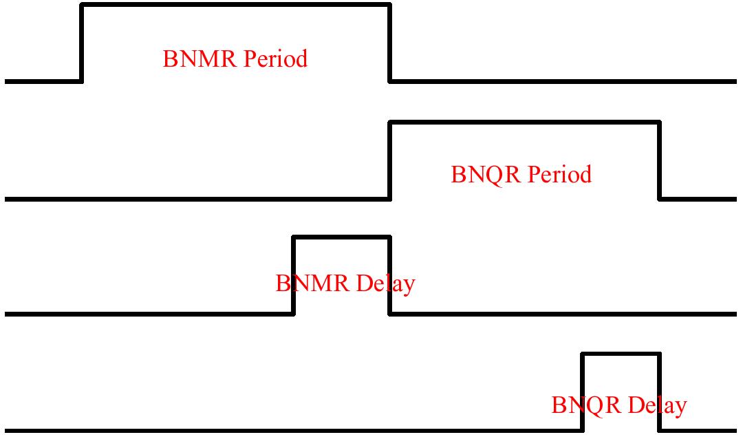
- BNMR controls the IMS
kicker for the time (BNMR
Period minus BNMR Delay), therefore make sure
that when setting up your PPG parameters in the BNMR
DAQ, the requested beam delivery falls within this time
range. Similar considirations apply for BNQR.
- The Helicity flip request sent from BNMR is actually executed at the begining of BNQR Delay, therefore make sure that you give a long enough BNQR delay so that EPICS command and the actual flipping are fully executed during this delay. Similar considerations apply for BNQR.
- At some point the
helicity will be flipped once every full cycle,
meaning once every (BNMR Preiod+BNQR Period). This
point is important as the best test that you did things
right. If not, your timing is incorrect.
- Change the timing only when "scheduled switching
disabled" (1).
- The "Kicker Control Status" indicates that DAQ3 is disabled (2) and that IMS
kicker is enabled
(3). You do not need to
enable either BNMR or BNQR, this will be done
automatically.
- The "ILE2A:XCB2 Switch Status" shows no fault (the fault is black not green).
Setting up the Timing Diagnostics Striptool
Within EPICS, start a striptool (epics main page:
isac_menu, utilities menu) for each DAQ. Load in the
standard striptool format for the corresponding DAQ using
the dropdown menu from the top left of the striptool
control dialog called "File" choose "Load" then type into
the directory field /home/bnmr/. In this directory, there
are both the bnmr_switch.stp and bnqr_switch.stp strip
tool configurations. Choose the appropriate one, and a
strip plot window like this will appear. This is useful in
diagnosing timing problems with dual channel mode.
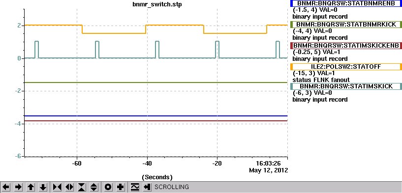
The EPICS parameters in this striptool are:
BNMR:BNQRSW:STATBNMRENB
BNMR is enabled,
this is TRUE (1) during the BNMR period
BNMR:BNQRSW:STATBNMRKICK
This is TRUE when beam is being kicked to BNMR
BNMR:BNQRSW:STATIMSKICKENB
This is TRUE when the Kicker (downstairs) is enabled, this
means beam can be kicked upstairs.
ILE2:POLSW2:STATOFF
This alternates with the flipping of helicity
BNMR:BNQRSW:STATIMSKICK
This shows when beam is coming through the Kicker from
downstairs
Setting up the DAQ
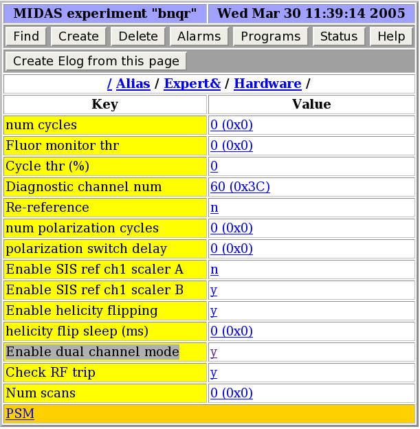
Normally in single channel mode a PPG cycle is started with an internal trigger from the PPC (software). In order to run the DAQ in dual mode, the PPG has to be setup to accept an external trigger (hardware) to start its cycle. This trigger comes in the form of a NIM signal lasting for the BNMR or BNQR period for the corresponding DAQ. The PPG is triggered on the leading edge of this signal.To set both DAQs to run in dual mode, follow the "Expert" link on the DAQ status page, then follow the "Harware" link and set "Enable dual channel mode" to "y":
The IMS kicker control box:
The "IMS kicker control" box is the box that gives permision
to either BNMR or BNQR to control the kicker, depending on
which side is recieving the beam. It also generates the
signal sent to either BNMR or BNQR DAQ to announce that beam
is ready for the appropriate side. This is box is a
green/black box located on the rack under the kicker patch
panel. BNMR and BNQR do not use the old kicker connection
anymore and we have a dedicated kicker connection for both
systems, controled by the control box as described above (do not make any changes on the
patch panel).Currently (2012) this box has been moved and the kicker patch panel rack is no longer on the floor near 8pi. The Kicker control box is in the first set of electronics on the mezannine near the counting room. It is near the bottom of the rack.
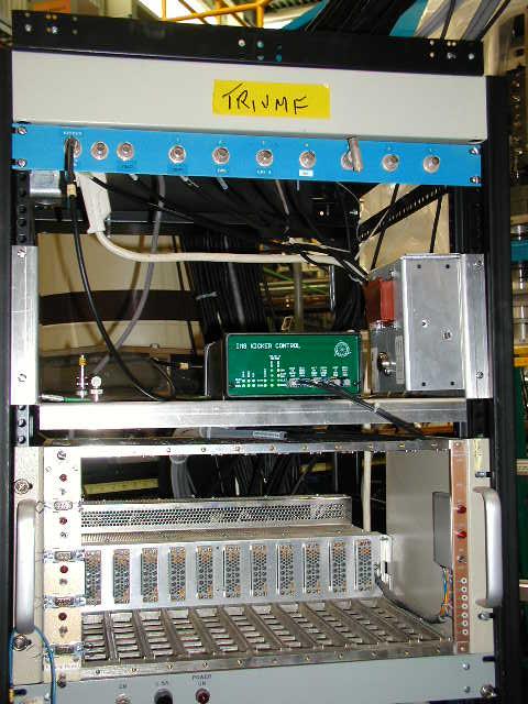
Old location
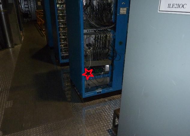
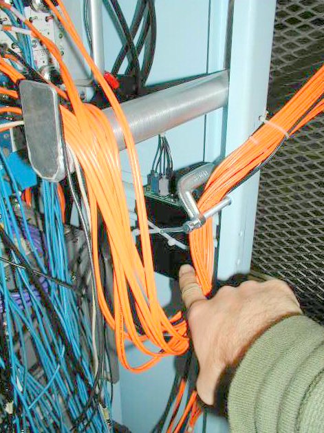
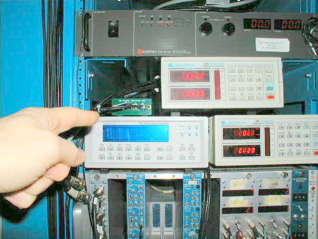
The beam ready signal coming out of the IMS kicker control box is sent over a fiber optic link to either BNMR or BNQR. Similarly, the kicker signal sent from the BNMR and BNQR DAQs is sent into the main control box over a fiber optic link. These optic signals are converted to NIM signals at both BNMR and BNQR ends using a small "IMS kicker isolation box". The location of these boxes is shown in the following pictures:
 |
 |
| Location of BNMR IMS kicker isolation
box |
Location of BNQR IMS kicker isolation box |
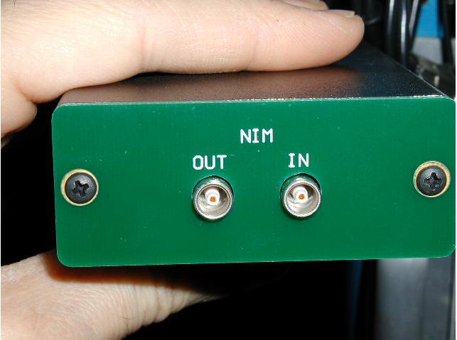 |
| NIM "IN"
(kicker from DAQ) and "OUT" (beam is ready
to DAQ) connectors on the IMS kicker
isolation box. |
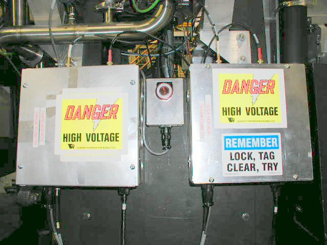
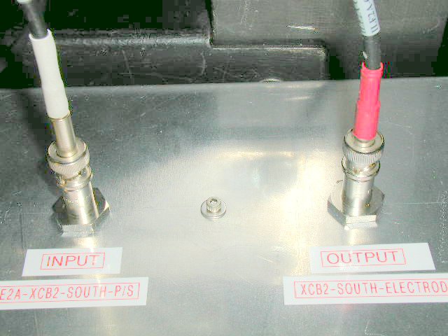
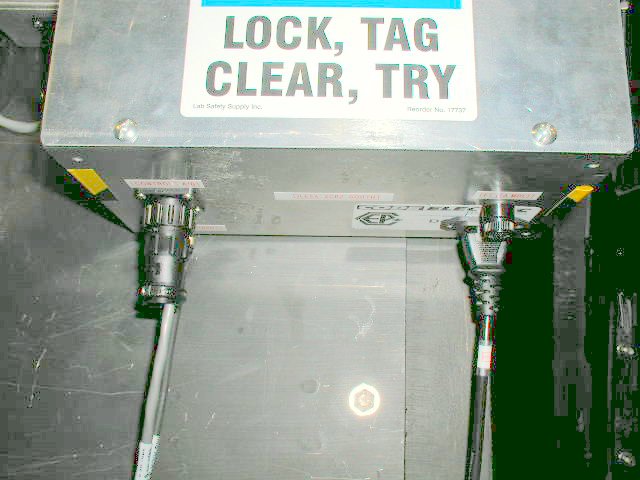
The fast switch XCB2
In order to produce the fast switching XCB2 was modified. Previously, the north and south plates were connected to opposite polarity power suplies, and in order to switch beam delivery from BNMR to BNQR the polarity of the plates was exchanged using a relay, which is too slow and has a short life making it useless for our needs.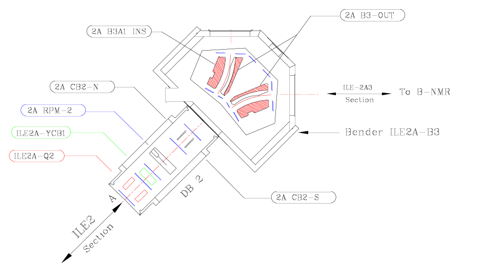
 |
 |
Setting up and Debugging the Timing:
One must set the PPG parameters appropriately to get dual channel mode to work correctly. A common problem encountered when the timing is not working is that beam pulses are not alternating correctly. This can result in one of the DAQs collecting only one helicity. There are overall constraints on the cycle timing (determined by the PPG parameters) that are set by the EPICS timing settings for scheduled switching (see above). If the DAQ cycle is too long, it will ignore any new start signal (external trigger) provided to it and skip a cycle.
The striptool is an essential way to debug such problems (see above).
SLR Mode (aka T1 or mode 20)
The PPG parameters that control the cycle timing are prebeam, beam on, beam off time. Let's call the sum of these times the Cycle time (one for BNMR and one for BNQR). Note: The "Helicity Flip Sleep Time" is IGNORED in dual channel mode. This is because with any reasonable timing, there will not be any old 8Li of the opposite helicity at the time the trigger occurs.
- The overall time (BNMR period + BNQR period) must exceed the maximum of (BNMR cycle time, BNQR cycle time).
- Each of (BNMR period - BNMR delay) and (BNQR period - BNQR delay) must exceed the corresponding "beam on" time.
- We are usuall using delay times of 2 seconds. This is enough, but may be more than necessary.
An example: (May 2012
Both BNMR and BNQR period = 8.5 seconds each (with 2 second delays).
We have the BNQR cycle time of 13.1 seconds and BNMR cycle time of 16.1 seconds.
The overall timing between DAQ triggers is thus 17 seconds, comfortably more than the longer DAQ cycle time.
BNMR uses a 4 second beam pulse which is also comfortably shorter than than the 6.5 seconds available, while
BNQR uses a 1 second pulse, also much smaller than the available 6.5 seconds.
In these conditions, each experiment gets a pulse every 17 seconds which is about the same duty cycle as either one operating individually in dual channel mode. Note the cycle time in single channel mode is longer by the helicity flip sleep time (usually 4 seconds), so each experiment is getting data at about the same rate, but both experiments are running simultaneously!
Going Back to Single Channel Mode:
It may occasionally be necessary to go back to single channel mode, e.g. to tune or do a 1f (or other integral mode) measurement on one side or the other.
To do this:
- make sure both DAQs are set to "n" on the eneable dual channel mode.
- make sure the helicity flip sleep time is set to the appropriate value.
- make sure the operator has switched off "scheduled switching"
- make sure the operator toggles the manual switch back and forth bNMR to bNQR
- then make sure that the operator has sent the beam to the correct experiment.
2e Mode
The cycle length in 2e mode is determined by its PPG parameters. As above, one has to be certain that the cycle time fits in the corresponding period. More details need to be filled in here.
Page last modified: 05/13/12 01:01 by Andrew MacFarlane.