The ISAC β-NMR HomePage
| Introduction to β-NMR |
Publications |
Students Projects |
Contacts |
| Technical Information |
Data Acquistion |
Approved Experiments |
Internal Page |
| Related Links |
BNMR Wiki |
Data Analysis |
Photo Album |
|
|
The High and Low Field Spectrometers
 2p2P1/2
occurs at about 671 nm. There is time for about 10–20 cycles of
absorption and spontaneous emission which lead to a high degree of
electronic and nuclear spin polarization. The final step is to strip
off the valence electron by passing it through a He gas cell. So far
the highest nuclear polarization achieved is about 80% with an overall
transmission efficiency of about 20%. Typically one operates with 60%
polarization and 33% transmission.

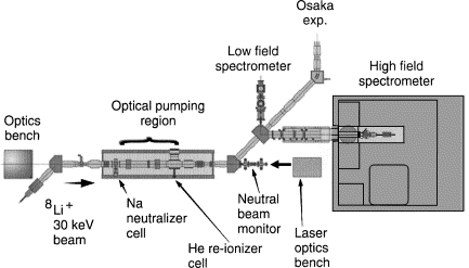
Fig. 1. Layout of the polarizer and β-NMR instruments at ISAC.
The polarized 8Li ion beam
is then passed through two
45° electrostatic bending elements which route the beam into one of
three experimental stations. Since the beam optics are all
electrostatic the polarization direction is unchanged by these bends.
Consequently the beam entering the high field spectrometer is
longitudinally polarized; whereas at the two other stations the beam is
transversely polarized.
The High Field Spectrometer
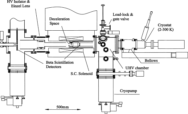
The section just before the high field spectrometer has three electrostatic Einzel lenses and three adjustable collimators which control the beam spot on the sample. A schematic of the spectrometer is shown in Fig. 2. The polarized beam enters from the left and passes through a hole in the back detector before entering the last Einzel lens at the entrance to a high homogeneity 9 T superconducting solenoid. The beam spot at the center of the magnet is a sensitive function of Einzel lens voltage, magnetic field and beam energy. Images of the 8Li beam at the sample position were obtained using a plastic scintillator and a CCD camera. These show that the beam spot is 3–4 mm in diameter.

| Fig. 2. High field -NMR spectrometer at ISAC. The beam enters from the left, passes through an aperture in the backward scintillation detector and is focussed onto the sample in the center of the 9 T superconducting magnet. Betas are detected with two scintillation counters centered on the axis of the superconducting solenoid. |
One of the most important features of the spectrometer is that the ions can be implanted over a wide range of energies (0.1–90 keV) corresponding to an average implantation depth of between 1 and 400 nm respectively. This is accomplished by placing the spectrometer on a high voltage platform which is electrically isolated from ground. The energy of implantation is controlled by adjusting the platform bias voltage. Note the grounded tube surrounding the electrode of the Einzel lens which extends into the bore of the magnet. The deceleration occurs as the beam exits this gold plated copper tube.
The high field spectrometer has longitudinal geometry such that the polarization and magnetic field are both along the beam axis. This is necessary for measurements in high magnetic fields where both the incoming ions and outgoing betas are strongly focussed by the magnet. The forward detector is on the beam/magnet axis and is located several cm downstream of the sample. In order to detect betas in the backward direction (opposite to the beam direction) it is necessary that the detector be outside the magnet since the betas are confined to the magnet axis while inside the magnet bore. Although the solid angles subtended by the two detectors in zero field are very different they have similar detection efficiencies in high magnetic fields due to the focussing effect of the solenoid.
Many experiments will be performed on
materials at cryogenic
temperatures and so an important design specification is the UHV vacuum
requirement necessary to avoid a buildup of residual gases on the
surface of the sample. Also since the low energy beam cannot pass
through any windows the final leg in the beamline is also UHV
compatible. Differential pumping with large cryopumps is used to reduce
the pressure from 10-7 Torr upstream of the spectrometer to
a
design goal of 10-10 Torr in the main chamber. The sample
cryostat is mounted on a large bellows so that it can be withdrawn from
the magnet bore in order to change the sample though a load lock on top
of the main vacuum chamber (see Fig. 2).
Plastic scintillation detectors are used to detect the betas from 8Li  8Be +νe + e-
for which the end point energy is 13 MeV. Since beta rates can reach 107/s
the detectors are segmented to reduce rate dependent distortions in the
spectra due to dead time. The plastic scintillators and light guides
are
held in reentrant stainless steel housings with thin stainless steel
windows, isolating the detectors from the UHV vacuum chamber, but
allowing transmission of the low energy betas.
The Low Field Spectrometer
A discription of the low field spectrometer is in progress.Page last modified: 07/23/09 02:45 by Andrew MacFarlane.